6th Consensus on 16 Approved Methods of Implant Placement in Corticobasal® Implantology
Copyright: International Implant Foundation IF®, Munich, Germany 2018/2019/ 2020; this 3rd version of the document has been revised and approved August 2021.
In an effort to standardize treatments modalities, the International Implant Foundation (Munich/Germany) releases this Consensus on 16 Methods in basal/strategic (cortical) Implantology. This consensus document only describes the best practices without recommending a specific number of implants per jaw or segment. It should be understood, however, that the number of implants used will typically be higher compared to treatment plans in conventional dental implantology, including: in order to meet the patient‘s request for immediate loading.
Strength: S3 (evidence based, systematically developed consensus guideline).
Other applicable documents:
- General rules for treatments in the trauma field and in orthopaedic surgery (AO-Principles)
- Indications and Treatment Modalities with Corticobasal® jaw implants. IF Consensus Document 2019, published in Ann Maxillofac Surg 2019; 9:379-86.
GENERAL METHODS
Methods 1
Method 1a
Multidirectional insertion of (one-piece) implants, whereby the implants are inserted (as far as possible) at an angle to each other (i.e. not parallel). To enable the insertion of fixed bridges, the following steps are carried out:
- The abutment heads (Fig. 1-2) are parallelized by bending the shafts of the implants (Fig. 3, 4, 7, 9, 11, 16b) to accommodate the prosthetic restoration. Or:
- Angle adapters (as intermediate elements) are cemented. Or:
- By grinding the large abutment heads, parallelism is created.
- Prosthetic constructions and implants are connected by prosthetic screws (for the Multiunit-Design of Corticobasal® implants)1.
Method 1b
The stability of the BIPS is achieved as follows:
- obligatory placement of implants in strategic positions
- adding stabilizing implants in other parts of the treated jaw bone.
- Complete penetration and anchoring of the force-transmitting thread in the 2nd and possibly 3rd cortex (i.e. not only in the 1st cortex which is used in crestal implantology) is mandatory. As a result, both extrusive and intrusive forces are safely transmitted into the cortical bone.
- If necessary, combination with polished compression screws.
Method 1c
Anchorage of implants in the 2nd or 3rd cortical, independently from “alveolar bone”. Preferred areas of anchorage are resorption stable regions of corticals.
Method 1d
Placement of Corticobasal® implants in severe and active periodontal involvement. Under the protection of strong topical disinfectants, the teeth and then the periodontally affected soft tissues are removed. Corticobasal® implants are inserted immediately and then splinted using a rigid prosthetic construction2, 3, 4.
Method 1e
Spongious, alveolar bone areas are avoided for anchorage. Achieving “osseo-integration” is not the primary aim of the treatment with the Corticobasal® implant.
Method 1f
Fixation of polished implant bodies made from implantable material with the aim of achieving mechanical anchorage in cortical bone areas of the maxillo-facial skeleton. Subsequent splinting by the prosthetic construction in an immediate loading protocol.
Method 1g
Creating anti-rotation features for an implant by bending intra-osseous parts of the shaft of the implant.
Method 1h
Achievement of primary stability through the use of enosssal / apical wide implants, the threads of which generate additional vertical bone condensation.
Method 1i
Anchorage of Corticobasal® implants in transplanted bone5, 7.
SITE-SPECIFIC METHODS
Methods 2
Method 2a
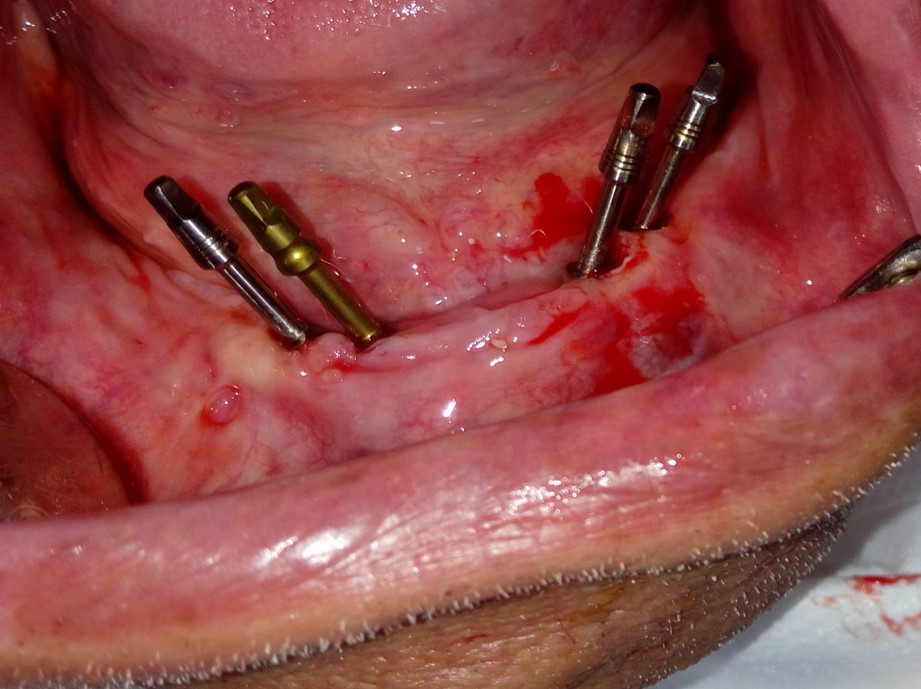
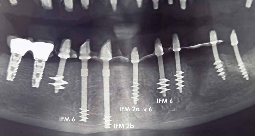
Placement of implants between the mental nerves (in anterior, edentulous mandibles), without necessity for anchorage in the 2nd (basal) cortical of the mandible. Threads of implants (usually two implants per side in regions 3 and 4) are placed into the chin area, converging towards the midline and avoiding thereby the mental nerve. The implants on each side are parallel to each other or slightly diverging.
Fig. 1 Placement of implants between the mental nerves (in edentulous lower jaws) with or without the need for anchoring in the 2nd (basal) cortex of the lower jaw.
This positioning and angulation has three advantages:
- The threads are in heavily mineralized bone
- The N. mentalis can be avoided
- The span to the heads of the distal implants is reduced
Method 2b
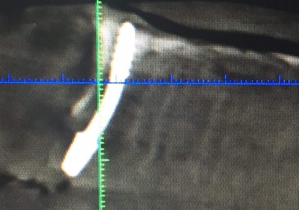
Endosseous positioning of the Corticobasal® implant in the inter-foraminal region, using the caudal cortical of the mandible for anchorage. Full or partial penetration of the caudal cortical of the mandible by the drill; retention of the tip of the implant in this cortical or through this cortical.
Method 3
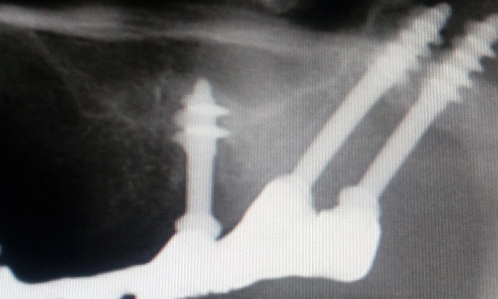
Anterior anchoring of segmented bridges with the insertion of one or two long Corticobasal® implants in the gap between the root of the canine and the mental foramen, Fig. 3. The threads of the implant extend under the root of the canine. The implant will extend to the caudal cortex of the mandible and can be anchored where necessary to achieve stability.
Fig. 3 Anterior anchoring of a segment with one (or 2) Strategic Implant® which reach into the gap between the root of the canine and the exit point of the N. Mentalis.
Methods 4
Method 4a
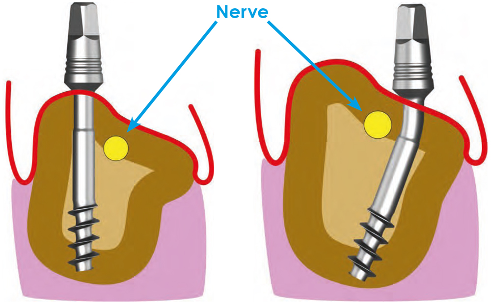
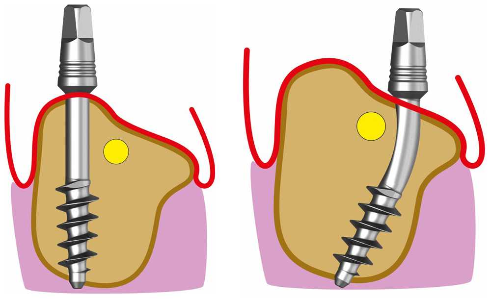
Nerve-Bypass: Endosseous positioning of the Corticobasal® implant in the distal (proximal) lower jaw, bypassing the inferior alveolar nerve on the lingual or vestibular side, Fig. 4, but without drilling through the caudal cortex of the horizontal branch of the lower jaw.
Fig. 4a 1-4
Nerve bypassing in the distal mandible
Without penetration of the caudal cortex (exception)
Thread diameter 2.7 - 3.5 mm
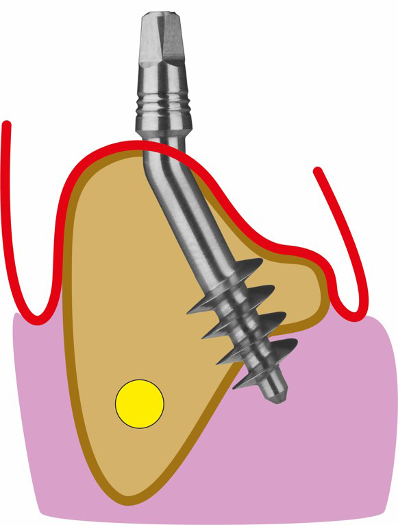
Method 4b
Nerve-Bypass: Endosseous positioning of the Corticobasal® implant in the distal (proximal) lower jaw, bypassing the inferior alveolar nerve on the lingual or vestibular side, if necessary, Fig. 4, with penetration and retention of the tip of the implant in or through the caudal cortex.
Fig. 4b 1-4
Nerve bypassing in the distal mandible
With penetration of the caudal cortex (exception)
Thread diameter 3.5mmd or wider
Methods 5
Method 5a
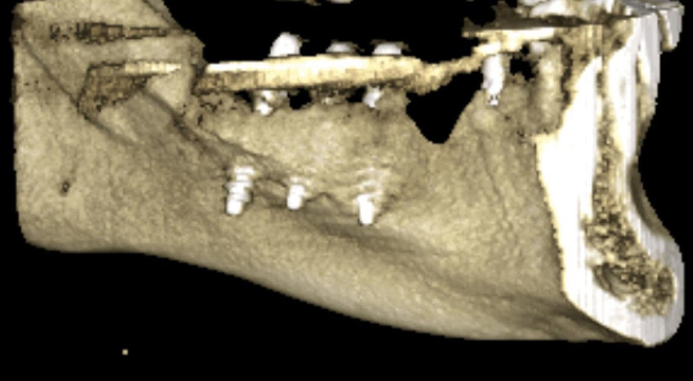
Lingual cortical anchoring in the distal lower jaw: Implant insertion with anchoring of the load-transferring threads in the lingual bone undercut below the mylohyoid ridge (where applicable, Fig. 5a-1, 5a-2) in order to achieve a really penetrating anchorage. The apical thread of the implant must be completely anchored in the lingual cortex and will partially protrude beyond it. The implant tip and possibly parts of the thread are thus in the space of the floor of the mouth. The inferior alveolar nerve runs caudally or vestibularly to the implant body. Typically, two or more such implants are placed distal to the mental nerve (i.e., in the proximal, horizontal part of the lower jaw). Typically, the tilt of the heads of these implants (before bending) is towards the front implants. For parallelization, the heads of these implants are bent proximally (i.e. parallelized with respect to the anterior implants).
Fig. 5a Anchoring in the lingual cortex in the distal mandible.
Fig. 5a-2 Three correctly inserted implants in the posterior mandible, with penetration of the lingual cortex. The thread areas are partly in the floor of the mouth.
Method 5b
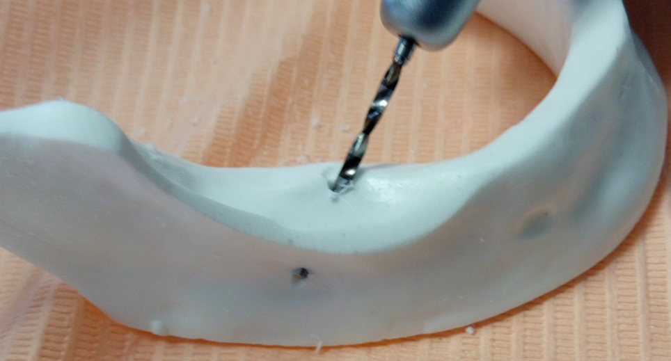
Vestibular cortical anchoring in the distal lower jaw: Implant insertion with anchoring in the vestibular, proximal cortical bone as the 2nd cortical and crestal of the inferior alveolar nerve, Fig. 5b.
Fig. 5b Vestibular cortical anchorage in the lower jaw.
It is important to drill this hole with the straight handpiece.
Method 5c
Vestibular cortical surgery in the distal lower jaw, with the implant running below the mandibular nerve: This method is used when the inf. alveolaris is far crestal, and when the distal mandible is wide and high enough to perform this type of placement.
Fig. 5c Vestibular or lingual cortical anchorage in the distal lower jaw, where the implant body runs caudal to the N. alv. Inferior.
Method 6
Placement of a Corticobasal® implant with the aim of providing palatal / lingual and vestibular support that extends into the cortex without using the second cortical bone layer in the vertical direction, Fig. 6-1. Main areas of application:
- Extraction sockets of mandibular and maxillary premolars.
- Lower and upper front teeth, Fig. 6a, b.
- Tuberosity of the upper jaw.
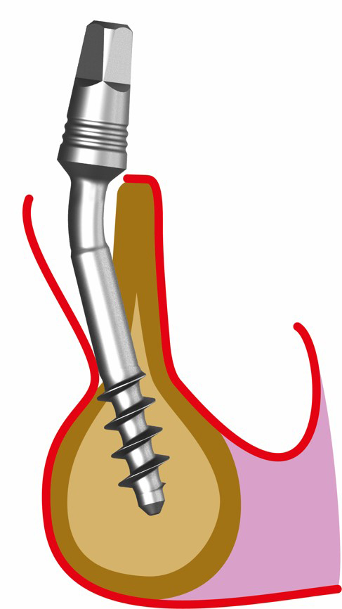
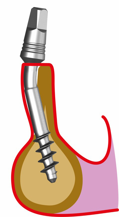
Fig. 6a Insertion of a cortical implant with anchoring in the vestibular and lingual cortex without using the 2nd cortex in the axial direction.
Fig. 6b Insertion of a cortical implant with anchoring in the vestibular and lingual cortex without using the regular 2nd cortex.
Methods 7
Method 7a
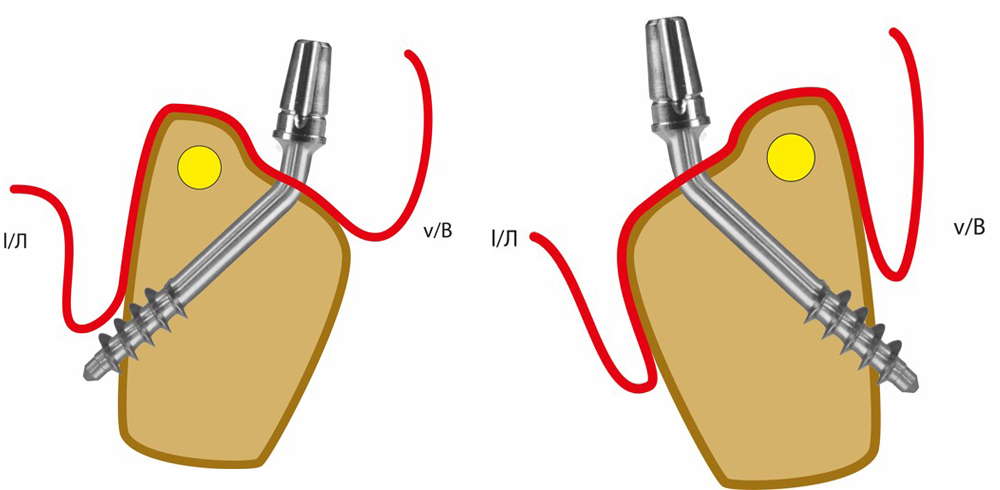
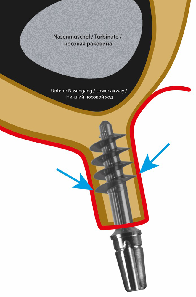
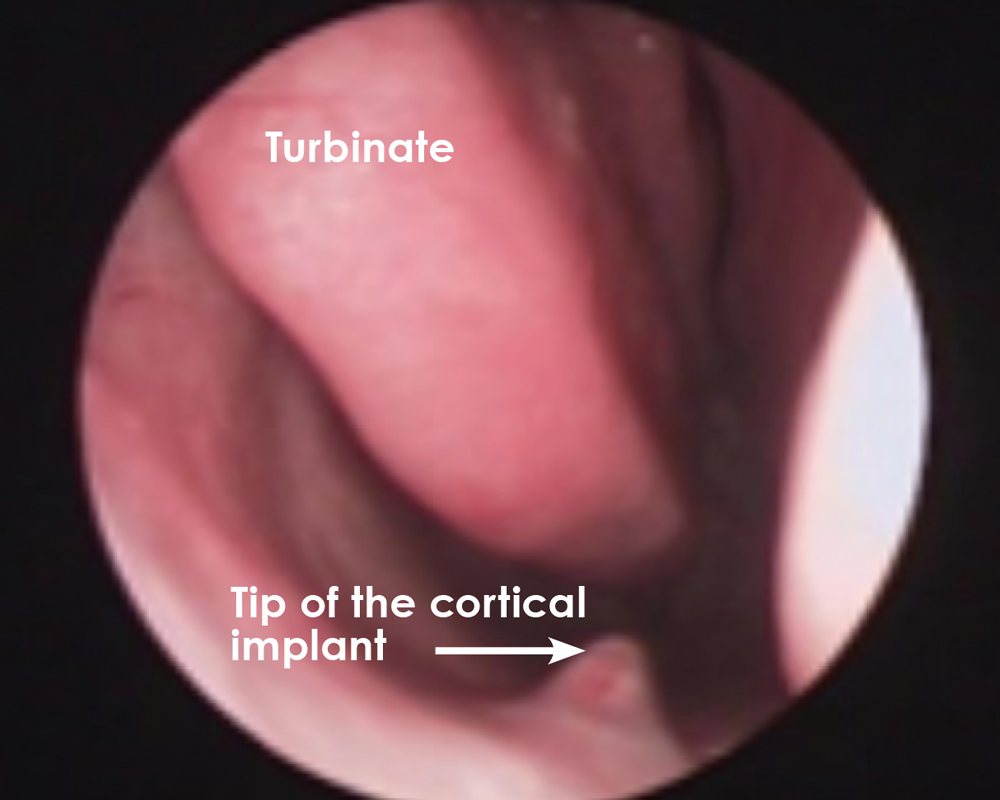
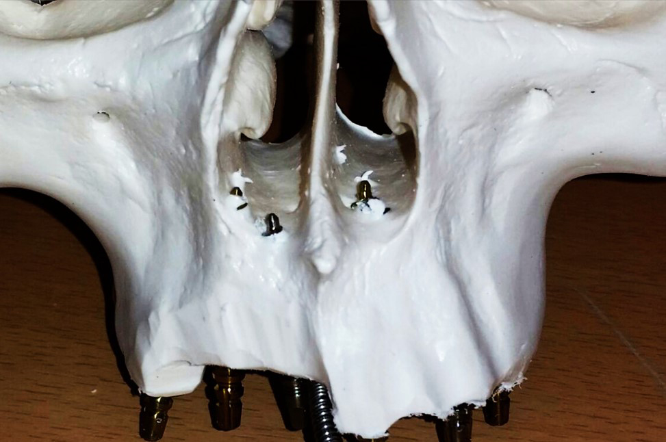
Penetrating anchoring of implants in the cortical floor of the nose. The implant is inserted vertically or obliquely through the maxillary alveolar bone and then anchored cortically. This technique involves the penetration of at least the tip of the implant into the mucous membrane of the floor of the nose. It is harmless if the polished implant tip and finally also part of the polished thread extend slightly into the lower airway or come into contact with the inferior turbinate. 7a-1, 7a-2, 7a-3.
Fig. 7a-1 In order to achieve secure anchoring in the nasal floor, the cortical implant must be screwed into the area of the nose. It is irrelevant whether the tip of the implant is covered by mucous membrane (as in this picture) or whether polished apical parts of the implant are exposed in the nose.
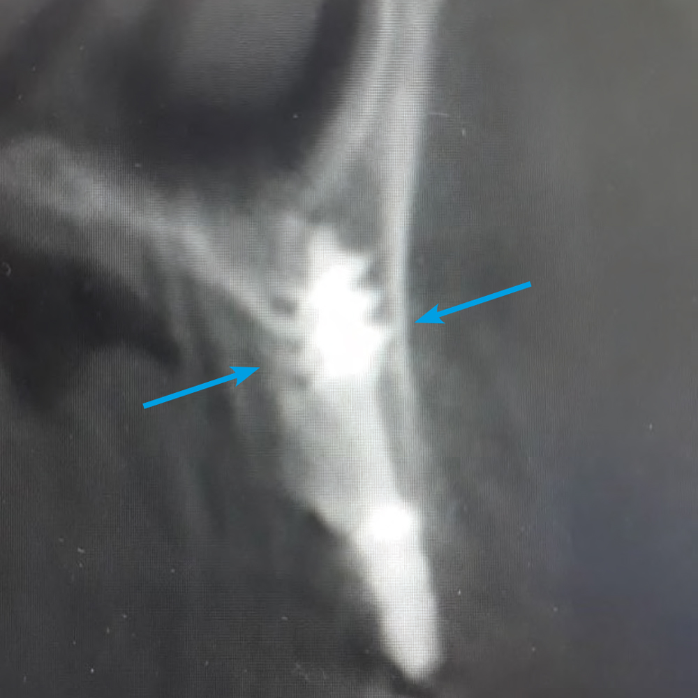
Fig. 7a-2 Anchoring of the implant in the nasal floor, with complete penetration of the cortex.
Fig. 7a-3 Anchoring of the implant in the nasal floor, with complete penetration of the cortex.
Method 7b
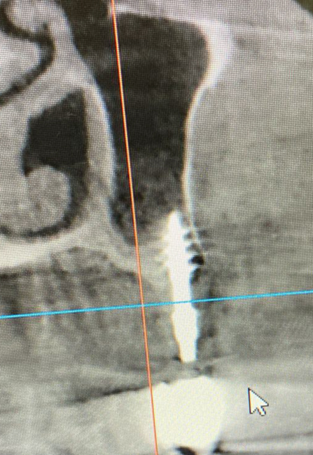
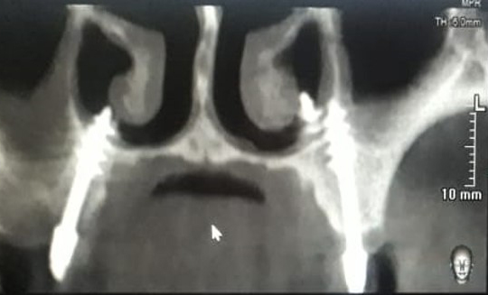
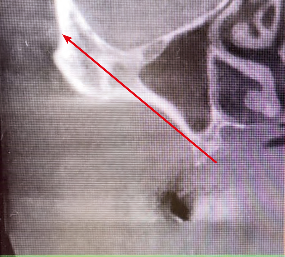
Implant insertion on the palatal side of the strongly horizontally atrophied alveolar bone („razor-sharp alveolar ridge“) without penetrating the actual alveolar bone for anchoring directly in the nasal floor, Fig. 7b-1. Method 7b is a special form of application of Method 7a, FIGS. 7a and b. Main areas of application: Regio 15-25.
Fig. 7b Direct insertion of the implant into the floor of the nose, bypassing the alveolar process (CT image).
Methods 8
Method 8a
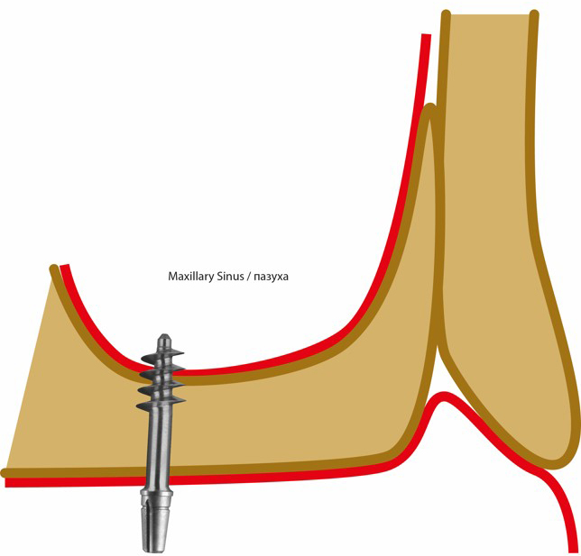
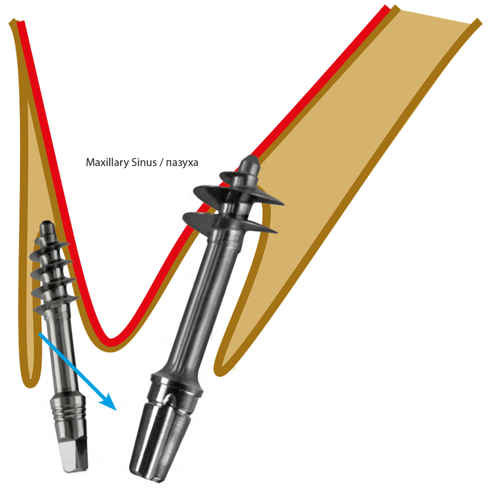
The cortical floor of the maxillary sinus as well as the Schneiderian Membrane are fully penetrated by the drill at medium speed (2.000 - 10.000 Rpm). The implant is chosen and positioned in such a way and length that approximately half of the apical thread of the implant will be inside the cortical borders of the maxillary sinus (i.e. cranial to the 2nd cortical), whereas the other half comes to lay in the spongious bone between the 1st and the 2nd cortical.
Fig. 8a-1 Anchoring the implant in the cortical floor of the maxillary sinus, IFM 8a.
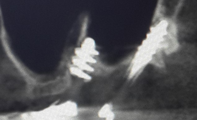
Fig. 8a-2 Anchoring the implant in the cortical floor of the maxillary sinus.
Method 8b
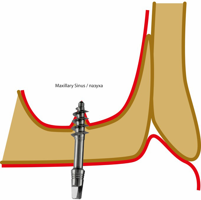
Use of an intra-sinus septum for multicortical anchoring of a Corticobasal® implant, including the penetration of parts of the implant thread into the bony floor of the maxillary sinus, Fig. 8b. The Schneiderian membrane can be penetrated.
Fig. 8b-1 Use of a septum in the maxillary sinus to anchor the implant, IFM 8b.
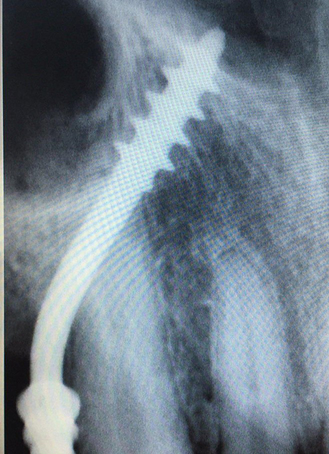
Fig. 8b-2 Use of a septum in the maxillary sinus to anchor the implant.
Methods 9
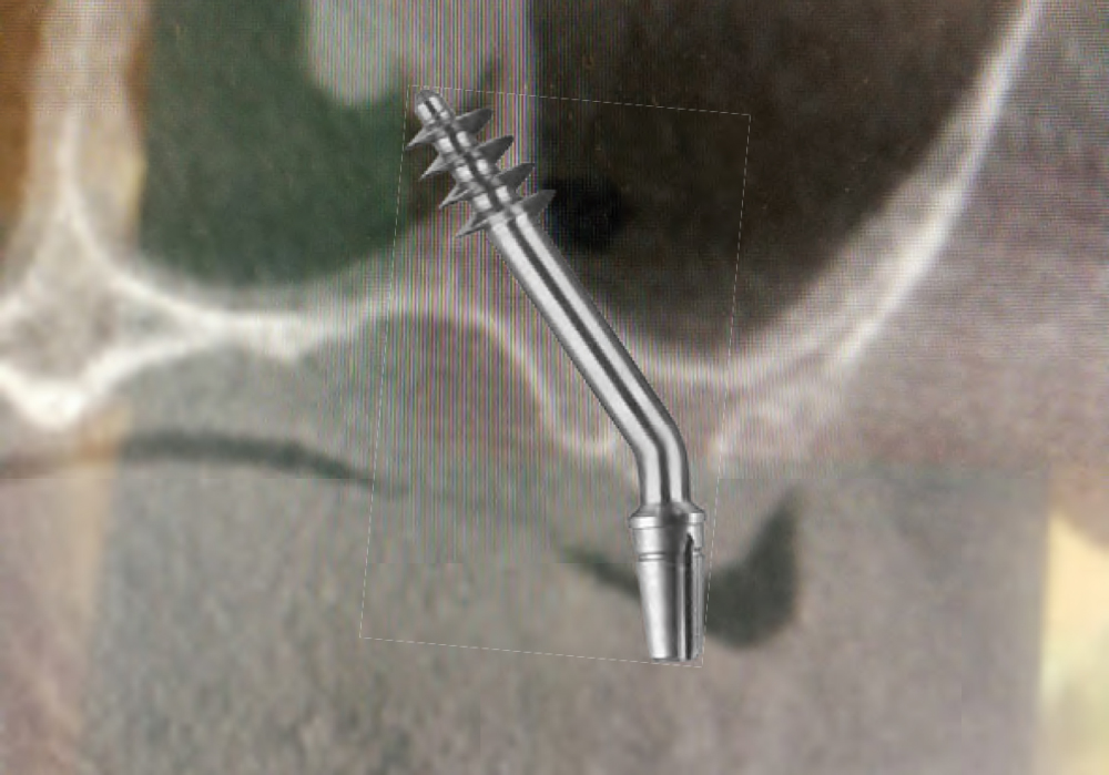
Fig. 9 The implant is anchored in the cortical floor of the nose, the implant being guided somewhat from region 14/15 on the palatal side of the canine root.
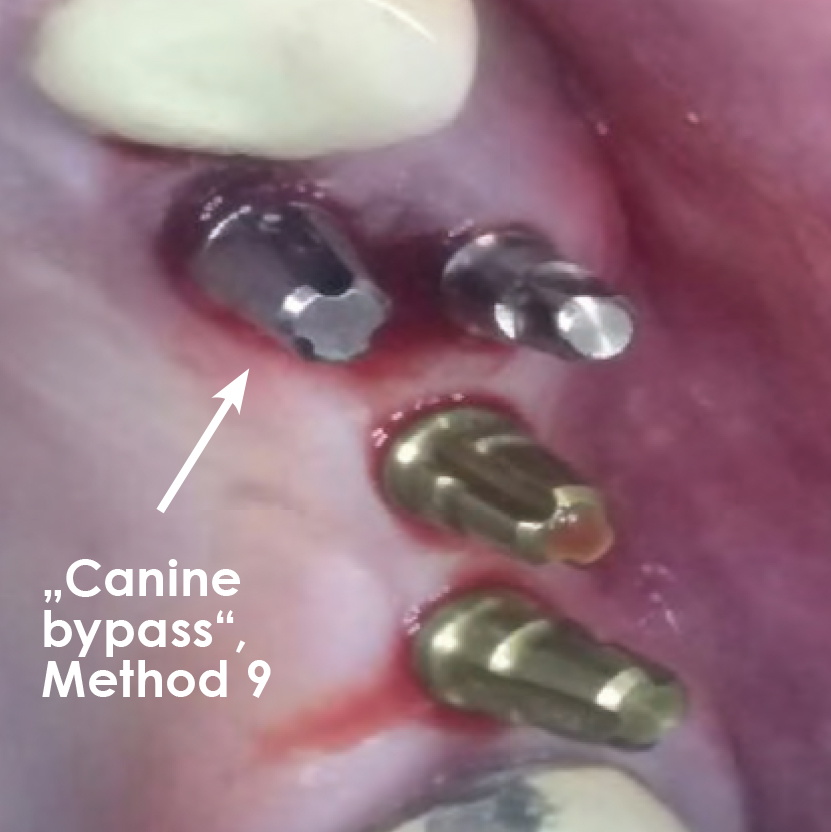
Method 9a
Bypassing the upper canine root: for anchoring an implant in the cortical floor of the nose, whereby the abutment head is positioned in the area of the first or second premolar and the shaft of the implant bypasses the root of the canine on the palatal side, Fig. 9. Method 9 is a special case of Method 7a or 7b and is used if the front segment (3-3) is not to be extracted.
Method 9b
Bypassing the upper canine root: Anchoring an implant in the raphe mediana of the upper jaw, with the abutment head positioned in the area of the first or second premolar and the shaft of the implant bridging the canine root palatally. Method 9a is a special case of Method 11b.
Methods 10
Method 10a
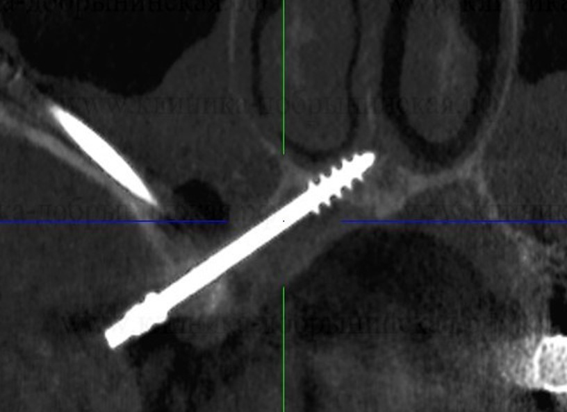
Placement of the apical thread of the implants in the cortex of the pterygoid plate of the sphenoid bone: It can be placed either directly into the pterygoid plate of the sphenoid bone or through the tuber of the maxilla and / or through the maxillary sinus6.
In an optimal end position, the tip of the implant penetrates the inner (medial) pterygoid muscle (between the wings of the pterygoid process), whereby secure anchoring against extrusion and intrusion and possibly compression of the holding bone is achieved. Corticobasal® implants or implants with compression thread components are used for this method. Fig. 10. Insofar as the implant lies in the fusion zone between the maxillary bone and the prerygoid process and between the wings of the pterygoid process (in the muscle attachment of the med. Pterygoid muscle), injury to the maxillary artery is excluded.
Method 10b
Double-Tuberopterygoid: Into the fusion zone between the maxilla and the pterygoid process of the sphenoid bone two parallel or slightly diverging implants are inserted.
Methods 11
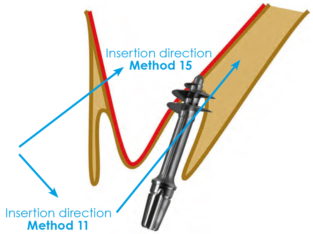
Method 11a
Anchoring in the bone on the palatal side of the maxillary sinus, without anchoring in the nasal floor or in the midline of the upper jaw, Fig. 11.
Fig. 11a-2 Insertion of the implant into the bone on the palatal side of the maxillary sinus.
Variants:
11a Anchoring with and without reaching the cortex of the nose
11b Anchoring in the median suture (raphe) of the maxilla
Method 11b
Anchoring of the implant from the lateral side in the midline of the upper jaw.
Fig. 11b Anchorage in the sutura palatina mediana.
Method 12
Anchoring the implant in the body of the zygomatic bone, Fig. 12:
- With a trans-sinusal approach (Fig. 12-1). Or:
- In a sub-periosteal approach directly into the body of the zygomatic bone. (Fig. 12-2).
Fig. 12 Insertion of the implant into the body of the zygomatic bone
- direct, extrasinusal
- transsinusal
Fig. 12-2 Extra-sinusoidal course of the implant if the anatomy is suitable for this procedure.
Recommended treatment approach, as far as anatomically possible.
Method 13
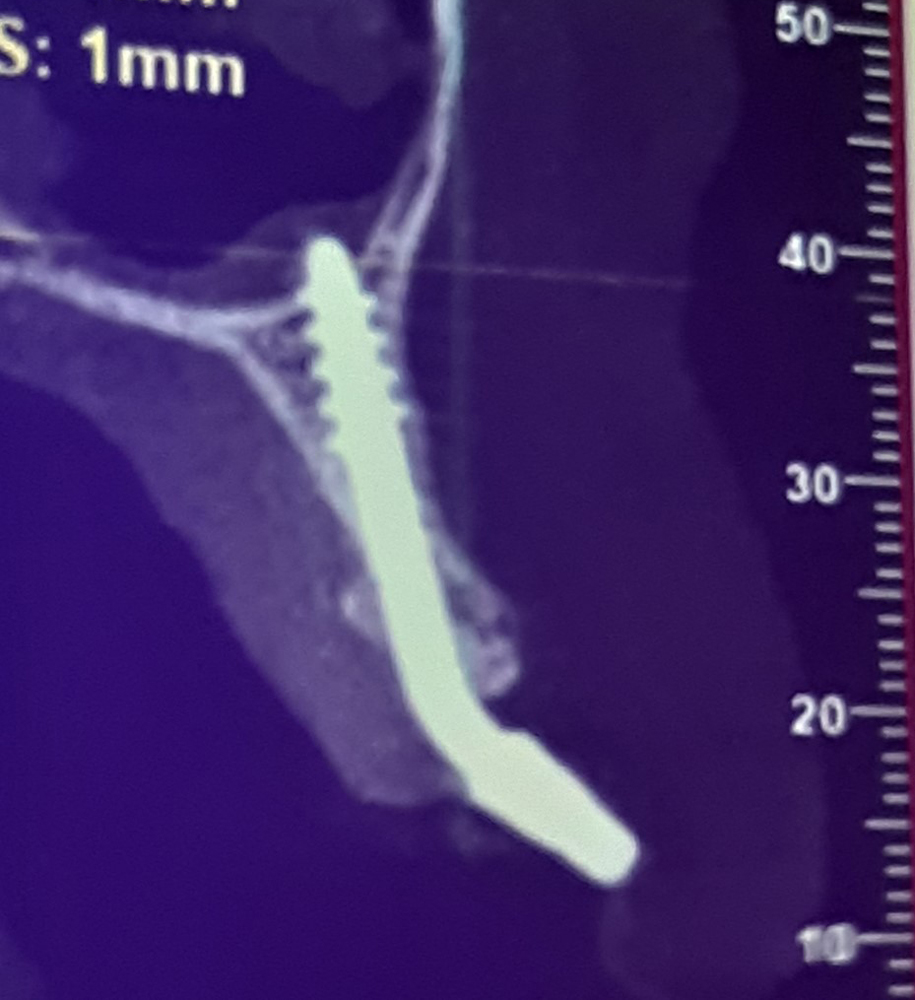
Placement of the implants vestibularly to the razor-sharp alveolar ridge in the anterior lower jaw. The typical implant diameter is 2.7 mm or 3.0 mm. Anchoring in the floor of the lower jaw, Fig. 13. Vertical parts of the implant run partially subperiosteally. The anterior caudal cortex can also be used for this type of implant anchoring. However, care must be taken to ensure that no blood vessel damage occurs and that a strategy to preserve the oral mucosa is used to cover the vertical implant struts, if possible.
Fig. 13-1, 13-2 Insertion of the implant vestibularly in front of the razor-sharp anterior alveolar ridge.
Diameter: 2.7 and 3.0 mm
Part of the implant runs subperiosteally. The threads anchor themselves in the base of the lower jaw.
Method 14
The anchoring of an implant in the fresh extraction socket of the first or second premolar with at least mesial and distal cortical anchoring in the cortex of the alveolus, Fig. 14. Use of the medial cortex of the lower jaw improves the anchoring.
Fig. 14 Anchoring of an implant in the fresh extraction socket of the 1st or 2nd lower premolar.
Diameter: 4.5 oder 5.5 mm, rarely 7 mm.
Method 15
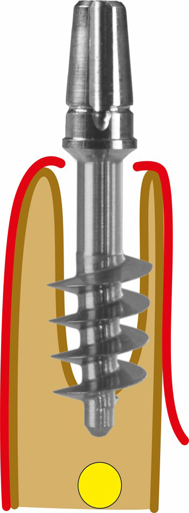
Insertion of a larger diameter implant into the fresh extraction socket of the palatal root of the upper first or second molar, Fig. 15.
Fig. 15 Insertion of an implant into the palatal root of an upper 1st or 2nd molar.
Methods 16
Method 16a
Insertion of two implants in the area of the upper first premolar, one implant being inserted palatally into the floor of the nasal cavity (Canine Root Bypass, Method 9), while the other implant is inserted in the area of the vestibular alveolus of the first premolar. Fig. 16a.
Fig. 16a Insertion of two implants into the two alveoli of a 1st upper premolar.
The implant inserted palatally runs towards the floor of the nose and palatally past the canine root (Method 9).
Method 16b
Insertion of two or three Corticobasal® implants in the area of the upper 1st or 2nd molar as an alternative to anchoring in the area of the tuberopterygoid if Method 10 cannot be carried out. Fig. 16b.
Fig. 16b Anchoring of 2-3 Corticobasal® implants in the aveole of an upper 1st molar.
Literature
1 Gaur V., Doshi A., Ihde S., Ihde A., Palka L. Multi-unit connection for the Strategic Implant®: an innovative way for achieving retrievability of prosthetics on fully polished single piece implants used in an immediate loading protocol. CMF Impl Dir 2020; 14: 3 - 34
2 Dobrinin O., Lazarov A, Konstantinovic V.K., et al. Immediate-functional loading concept with one-piece implants (BECES/BECES N /KOS/ BOI) in the mandible and maxilla- a multi-center retrospective clinical study. J. Evolution Med. Dent. Sci. 2019;8(05):306-315, DOI: 10.14260/jemds/2019/67
3 Lazarov A. Immediate functional loading: Results for the concept of the Strategic Implant®. Ann Maxillofac Surg 2019;9:78-88
4 Palka L., Lazarov A. Immediately loaded bicortical implants inserted in fresh extraction and healed sites in patients with and without a history of periodontal disease. Ann Maxillofac Surg 2019;9:371-8
5 Motaz Osman, Abdelnasir G. Ahmad, and Fadia Awadalkreem A Novel Approach for Rehabilitation of a Subtotal Maxillectomy Patient with Immediately Loaded Basal Implant-Supported Prosthesis: 4 Years Follow-Up ; Hindawi Case Reports in Dentistry Volume 2020, Article ID 9650164, 7 pages https://doi.org/10.1155/2020/9650164
6 Ihde S., Ihde A., Lysenko V., Konstantinovic V., Palka L. New Systematic Terminology of cortical Bone areals for osseo-fixated Implants in Strategic Oral Implantology; J.J.Anatomy, 2016, 1(2), 007
7 Fadia Awadalkreem, Nadia Khalifa , Abdelnasir G. Ahmad, Ahmed Mohamed Suliman, Motaz Osman; Prosthetic Rehabilitation of maxillary and mandibular gunshot defects with fixed basal implant supported prostheses: a 5 year follow-up case report. Int J. of surgery Case reports 68(2020) 27-31